Considerations for Self-Powered Data Centers
Installing prime-power on-site to reduce dependence on the local electric utility.
By Ben Standish
Colovore Director of Design & Engineering
Grounding Considerations for Prime-Power Data Centers
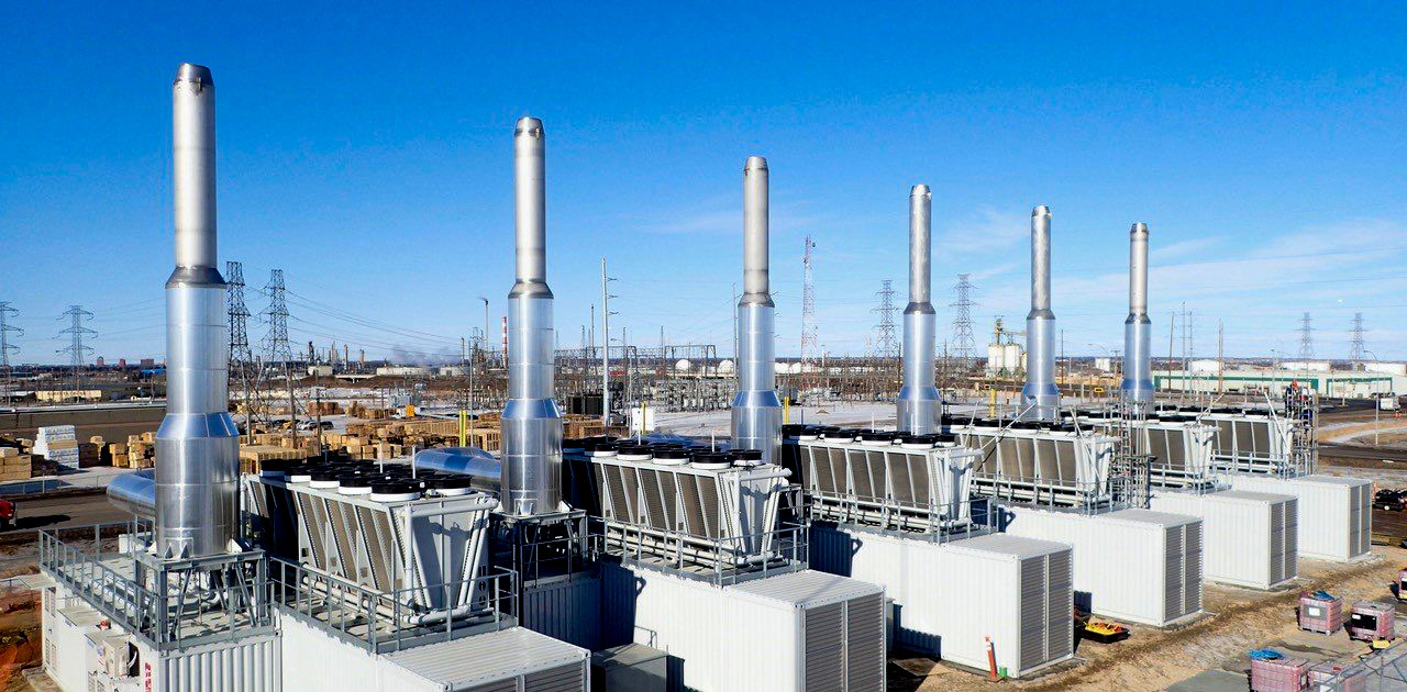
The era of self-powered data centers is upon us. Capacity constraints on the U.S. electric grid are driving data center developers to pursue a variety of revolutionary, onsite prime-power solutions including Small Modular Reactors (SMR), microgrids, and large-scale renewables + storage. Traditional high-capacity combustion turbines are being deployed as well. Simple-cycle and combined-cycle turbines that deliver hundreds of megawatts per machine have historically been the domain of heavy industry and utility peaking plants. Currently in development are massive new AI factories located on gigawatt data center campuses that will utilize gas turbines in parallel off-grid and grid-connected arrangements, with unit base ratings from 25 to 250 MW per generator or more.
Installing prime-power plants onsite greatly reduces or eliminates dependence on the local electric utility. On one hand this solution can bypass critical path hurdles such as utility substation construction, transmission line permitting, grid stability studies, and a myriad of environmental and societal challenges to expanding electric utility infrastructure for new data centers. However, these onsite power plants will face their own challenges including siting/permitting restrictions, a shortage of skilled plant operators and maintenance technicians, higher available fault currents with higher X/R ratios, and facility outage risks in cases where prime power replaces vast arrays of standby diesel generators. As prime-power gains traction the economics could improve through revenue generating opportunities such as ancillary services. This typically involves an independent power producer securing a contract to stabilize the local electric grid by providing frequency and voltage support using interconnected power generation assets. The prime-power data center market will take shape over the next several years as some of the larger, AI factory sites around the U.S. bring gigawatt-scale power generating capacity online.
This remarkable shift towards independent power production will be accompanied by the prolific growth of medium-voltage (MV) distribution systems. In the U.S., MV systems range from 2.4 kV to 69 kV – with most MV generators rated 5 kV or 15 kV, and the largest utility-scale generators (500 – 1,000 MW) operating at up to 25kV. Applications above 35 kV are typically limited to utility sub-transmission systems and rural distribution networks.
Typical Utility Service Interconnection
Most data center facilities interface with the serving electric utility at 35kV or less via multiple incoming feeders and MV switchgear supplying a scalable network of loop-fed transformers. Each transformer serves a modular low-voltage(LV, 600V and less) power block rated 2 – 4 MW per block. Electric utility substations in the U.S.almost invariably use solidly grounded, secondary wye windings in their substation transformers to serve MV distribution networks. Therefore, a data center’s onsite MV distribution system should have no intentional neutral-ground connections downstream of the incoming utility feeders. In rare cases, some utilities will require wye-grounded primary /wye-grounded secondary transformers in lieu of the preferable delta primary /wye-grounded secondary type. The delta primary transformer is generally preferred because the delta winding isolates the primary grounding network from the wye-grounded secondary. This effectively decouples any secondary ground fault current (zero-sequence current) from the primary source such that downstream secondary ground faults will appear as low magnitude line-to-line faults on the primary distribution system. This promotes better overcurrent coordination on both primary and secondary distribution systems, and improves primary distribution system stability during customer-side ground faults.
Prime-Power Grounding System
In contrast to the intentional absence of neutral-ground bonds in typical MV utility service interconnections, the installation of onsite prime-power generators will require a neutral-ground (N-G) bond at eachMV generator wye winding. This N-G bond is required at all “separately derived sources” by the National Electrical Code and is consistent with good engineering practice born of the hard lessons from industrial era ungrounded-delta power system failures.
Proper protection of MV generators involves making the N-G bond through a neutral grounding resistor (NGR). NGRs are installed between the generator neutral terminal and Earth primarily to limit ground fault current flow through the generator windings to a level well below the maximum fault current for which the windings are braced (alternator withstand rating). Most generators have very low zero-sequence impedance (1% to 5%) compared to positive and negative sequence impedances (10% to 20%) [2]. For the popular 2/3 pitch winding this is particularly important because it has negligible zero-sequence impedance – meaning ground fault current magnitudes supplied by the generator can easily exceed the alternator withstand rating. In this case, were the generator to supply a high magnitude (low impedance) ground fault, a solidly grounded 2/3 pitch winding could fail catastrophically. Done properly, there are other benefits to resistance grounding including reduction of arcing faults, increased equipment protection, and support for paralleling generators with different winding pitches – the NGR on each generator eliminates triple n harmonic currents from circulating between the generators.
The NGR is typically a low-resistance type that allows ground fault current magnitudes from 200 A to 1000 A to flow for actuating overcurrent protective relays [1][2]. Other neutral impedance-grounding options are available such as reactance grounding, high resistance grounding, or hybrid systems that rapidly switch from low to high resistance grounding for increased protection against internal winding faults after a faulted generator is cleared from the bus.
The Multi-Grounded Neutral Problem
The new era of prime-power data centers will have more complex grounding systems than sites that are served by a traditional MV utility service. With a potential mix of multiple generators, solar + storage inverter step-up transformers, and utility transformers all operating in parallel there exist several N-G connections that form a ground fault “island.” The N-G bonding system serving this island will not function properly unless all N-G bonds are of the same type – either all solid N-G bonds or all separately derived sources grounded through NGRs, but not a combination of the two methods. The essential engineering reference, IndustrialPower System Grounding Design Handbook, sums up the problem as follows:
“A ground-fault island comprising of multi-grounded solid-and resistance-grounded neutrals is fundamentally flawed, suggesting that its design and implementation be avoided. The fundamental problem is that the solidly-grounded source shorts out the neutral resistor, making it ineffective. Only when the solidly grounded source is relayed off, will the proper current flow in the resistor.” [3]
This situation is not intuitive – the misconception being that ground fault current supplied by a resistance-grounded source must flow through its NGR when the current returns to that source. Confusion can arise during short-circuit analyses - a tendency not to trust the results. A lack of clear understanding can also impact the approach to deriving and validating proper protective relay settings.
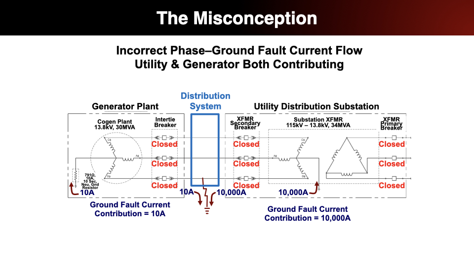
The example below is from an actual 13.8kV, 28MW gas turbine cogeneration system that operates on a major North American university campus. This system was analyzed as part of a campus wide power system study. To simplify the diagrams, the electric distribution system that serves the campus is not shown. The area between the Generator Plant and theUtility Distribution Substation enclosed in the blue box is considered the external campus distribution system. Therefore, the example ground fault could occur anywhere on the utility’s distribution system, or on the generator owner’s distribution system, downstream of the utility transformer. This same situation would be present at a prime-power data center where the onsite generation is designed to operate in parallel with the serving utility.
The Misconception
A few things to note about the multi-grounded neutral system presented in these diagrams:
1. The 34 MVA utility substation transformer has a solidly-grounded secondary wye winding, and the generator is grounded through an NGR. The gas turbine cogeneration plant operates almost continuously in parallel with the serving utility.
2. The 30 MVA generator is grounded through an NGR rated 10 A for 10 seconds. Being an existing installation the author had no insight into the engineering backstory that led to this design choice, but the NGR is incorrectly sized. A magnitude of 10 A is not enough faultcurrent to allow proper detection and fault clearing by the protectiverelays. An appropriately sized NGR forthis 30 MVA generator would be in a 400 A to 600 A range.
The fault current paths and magnitudes presented in this diagram represent a flawed analysis. During a ground fault in the distribution system, this diagram indicates the generator will supply only 10 A of fault current through its NGR, and the utility substation transformer will supply 10,000 A independently from the generator. In a multi-grounded neutral system the ground fault current does not necessarily return to its source through that source’s neutral terminal. The ground fault current path is impedance-dependent.
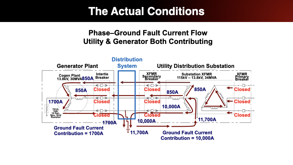
The Actual Conditions – Utility & Generator BothContributing
The currents in these diagrams were derived from ashort-circuit output report in SKM software. Please note that these are phasecurrents not sequence currents. The first thing to note is that none of theground fault current flows through the 10 A NGR. It is effectively shunted by the solidlygrounded utility transformer. Theutility N-G bond carries the ground fault return current for the summation ofgenerator + utility, and the generator ground fault current returns to thegenerator through the distribution system phase conductors.
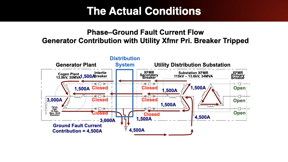
The Actual Conditions – Generator Contribution with Utility Xfmr Primary Breaker Tripped
It would be unusual for primary protection to trip before secondary on a utility transformer – this could be the result of poorly coordinated protection settings or relay mis-operation, but it is possible and the situation is informative regarding current flows in the ground fault island.
When the utility transformer primary breaker trips the 10,000A utility fault contribution is removed, and the secondary breaker remains closed. The transformer essentially becomes a wye-delta grounding transformer for the generator, and the generator’s ground fault contribution increases from 1,700 A to a maximum of 4,500 A due to the low impedance path for zero-sequence current to circulate in the transformer’s delta primary winding. Still no involvement from the NGR path because the utility transformer’s solidly grounded path is of far lower impedance.
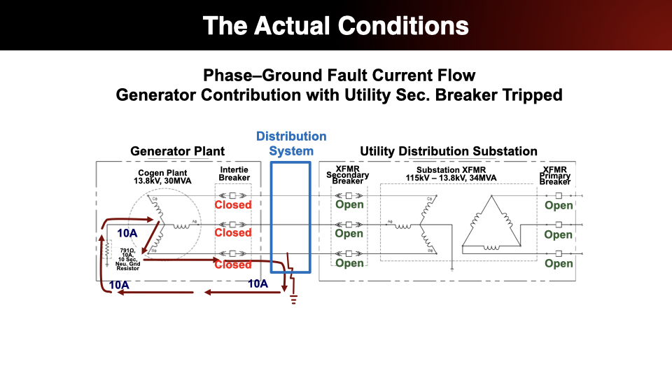
The Actual Conditions – Generator Contribution with UtilityXfmr Secondary Breaker Tripped
With the utility transformer secondary main breaker tripped the solidly grounded-wye winding is isolated from the generator. Only then does the generator begin supplying ground fault current through its 10 A NGR. As previously mentioned, 10 A is not an adequate magnitude for overcurrent protective relays to accurately detect fault current vs.load/imbalance/error current and clear the fault. With the NGR only rated to carry 10 A for 10seconds the NGR would likely overheat and fail open before the protection clears the fault.
Key Takeaways for Prime-Power Data Center Design
1. MV generators should be low resistance grounded with an NGR rated between 200 A and 1000 A depending on generator size.
2. All N-G bonds should be of the same type in a power system with multiple, separately derived sources that operate in parallel(either solid-grounding or resistance-grounding, but not both).
3. Realize that public utility substations are typically solidly-grounded. Interconnecting a utility source and a prime-power data center that uses resistance-grounded MV generators will likely shunt the generatorNGRs making them ineffective.
4. Ground fault protection design depends on multiple operational scenarios. Since the NGR carried no fault current the generator ground fault protection was not in play until the utility substation was tripped offline completely. The unintended consequence of shunting the generator NGR during ground faults requires a fresh look at the protective relay settings and methods of protection at multiple locations.
5. When modeling a utility source more detail is better. Most power analysis software allows the selection of a generic utility source node to represent the upstream utility. This was a limitation at the beginning of this analysis. Only after several phone calls and emails to the serving utility were we able to gain details about the utility substation transformer, substation bus configuration, and breaker sequence of operation. This information was essential to building an accurate model in SKM - allowing the true phase-current magnitudes and phase angles of the ground fault current path to be analyzed and understood.
Bibliography
[1] IEEE Std 142™-2007, IEEE RecommendedPractice for Grounding of Industrial and Commercial Power Systems (IEEE GreenBook™).
[2] Nelson, J. P., “System Grounding andGround-Fault Protection in the Petrochemical Industry: A Need for a BetterUnderstanding,” IEEE Transactions on Industry Applications, vol. 38, no. 6,November/December 2002.
[3] Dunki-Jacobs, J. R., Shields, F. J.,and St. Pierre, C., “Industrial Power System Grounding Design Handbook,” 2007.
Sign up for updates straight to your inbox
By subscribing you agree to with our Privacy Policy and provide consent to receive updates from our company.